Scheme
In order to measure the noise presented on Power-Lines for
frequencies higher than 1MHz, we developed the following pickup circuit,
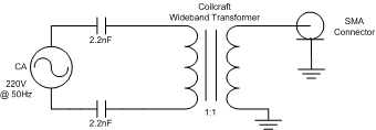
Figure 1 - PICKUP CIRCUIT USED TO MEASURE THE NOISE IN POWER LINES UP TO 500MHZ.
The 27µH inductance of the transformer and the two 2.2nF
capacitors, compose a high-pass filter with cut off frequency at approximately 0.9MHz. This
scheme was used to measure the noise spectrum for frequencies between 1MHz and 500MHz.
We were only interest to measure the noise, for frequencies between 1MHz and 100MHz. In order
to cut off frequencies higher than 100MHz we used an LC filter from Coilcraft with a cut
off frequency of about 150MHz. The filter is flat up to 150MHz and its attenuation increases up to
45dB at about 500MHz, were it starts to decrease down to about 25dB.
The pickup circuit presented in Figure 1 becomes:
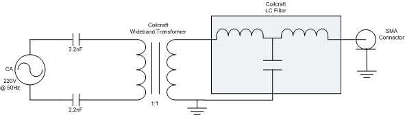
Figure 2 - PICKUP CIRCUIT WITH LC FILTER USED TO MEASURE THE NOISE IN POWER LINE UP TO 100MHZ.
Click in Figure to zoom.
Since the Digital Storage Oscilloscope used, couldn't measure up to 1mV/div we used one of two amplifiers. The first
amplifier used was the ZFL-500+ Amplifiers with a 20dB gain and the second amplifier used was
the ZFL-500LN+ Low Noise Amplifier with a 24dB gain.
The Figure below shows the final system used to measure the noise presented in Power-Lines.
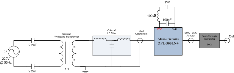
Figure 3 - FINAL SYSTEM USED IN PLC NOISE MEASURE.
Click in Figure to zoom.
In order to maintain the 50Ω impedance we used feed-trough termination with 50Ω impedance. This is useful for
connecting signals from 50Ω sources into instruments with high-impedance inputs like the oscilloscope used and also
prevents that the amplifier output becomes in open circuit and damaged him.
Figure 3 only presents the scheme for ZFL-500LN+ Low Noise Amplifier, however this amplifier could be replaced
by the ZFL-500+ Amplifier without changing the rest of the scheme.